How to inspect moulded plastic parts
Inspect cooled parts linked to each mould cavity, map defects to named features and check assembly with approved mating parts. Agree separate appearance and functional limits before production, then record results by cavity and batch. Coordinate the factory checks and reports through Cambridge China Bridge.
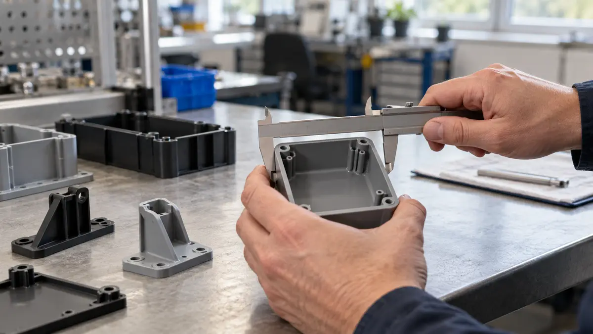
Keep samples linked to their mould cavity
Ask the factory for a cavity map and a reliable way to identify which cavity made each sample. Keep that identity attached to photographs, measurements and assembly results. If parts have no cavity marking, agree labelled collection at the press. Do not accept a mixed bag of selected good parts as evidence that every cavity performs consistently.
Include samples from each active cavity across the production run, including after restarts or adjustments. Record the tool identity, drawing revision, resin lot and collection time. Agree sample quantities and selection before inspection. The first-article inspection brief covers the wider approval record; the moulded-components guide covers factory qualification.
Map defects to the features they affect
Mark inspection locations on an annotated drawing or photograph. Name the visible face, rib, screw boss, latch, sealing edge or mating surface affected. Photograph the whole part for orientation and the defect in detail, with a scale. Keep the cavity identity visible in the record.
Use the checks below to describe the defect rather than guessing its cause. Ask the moulder to investigate repeated patterns by cavity and location. A photograph alone does not establish whether the tool, material, design or process needs changing.
| Defect | Where to look | What to record or check |
|---|---|---|
| Sink marks | Surface opposite ribs, bosses and thick junctions | Local depressions or gloss changes; compare appearance and check any affected mating or sealing surface |
| Flash | Parting edges, openings and insert boundaries | Projecting excess plastic; check clearance, sharp edges, loose material and obstruction |
| Short shots | Thin ends, rib tips, corners and small features | Missing or incompletely formed material; compare with the drawing and test the affected feature |
| Warpage | Broad faces, rims, long edges and mating surfaces | Bow, twist or rocking; measure using agreed supports and check assembly gaps |
Separate appearance limits from functional limits
Agree visible and concealed surface zones, lighting, viewing position and approved boundary samples showing acceptable and unacceptable appearance. Specify how sink marks and flash are judged in each zone. Use the visual defect limits guide for the viewing method rather than relying on a request for a good finish.
Write functional limits against the drawing and intended use: clearances, sealing surfaces, latch engagement, screw-boss integrity and permitted distortion. A concealed defect can still prevent assembly. An appearance concession should identify the affected batch and locations and should not silently relax a dimensional or functional limit.
Check cooled parts and actual assembly
Agree the cooling or conditioning period, inspection temperature, measurement supports and whether each feature is assessed freely or assembled. Use the same method for approval and production inspection. Avoid clamping a warped part flat unless that is the agreed measurement condition. Check suspect faces with a suitable reference surface or fixture and record the measured deviation.
Use approved mating parts with their revisions recorded. Check seating, gaps, alignment, latch operation and screw assembly under agreed conditions. Do not force parts together or trim them before the baseline check. Where sealing, retention or loading matters, agree a suitable test and record its result separately from appearance and dimensional measurements.
Working out your own order? Send us the product on WhatsApp and we reply the same working day: WhatsApp us
Make the report support a release decision
Request a report showing the samples examined by cavity, defect locations, measurements, appearance decisions and functional results. Flag a cavity-specific failure separately from the overall batch result so it cannot disappear in an average. The quality inspection guide explains inspection stages; add this moulding-specific checklist to the agreed inspection scope.
When a defect fails the agreed limit, identify and hold the potentially affected stock while the factory establishes its extent. Record sorting or rework instructions and retain failed samples. Inspect fresh cavity-linked samples after correction, including checks that the correction has not introduced another defect. Cambridge China Bridge's staff in China can coordinate records and checks; the buyer approves deviations and shipment release.
Frequently asked questions
Are sink marks always a reject?
Judge them against the agreed surface-zone limits. Also check whether the depression affects a mating or sealing surface. Acceptable appearance does not establish acceptable function.
Can the factory trim flash before inspection?
Record the as-moulded condition first. If trimming is approved, inspect the finished edge, cleanliness and fit, and keep reworked stock identifiable.
Why do I need samples from every mould cavity?
A mixed sample can hide a failing cavity. Keep cavity identity on each result so recurring defects can be traced and the potentially affected stock identified.
How do I check warpage in plastic parts?
Measure cooled or conditioned parts on agreed supports without forcing them flat. Then assemble them with approved mating parts and record gaps, seating and operation separately.